Project Detail
Mixing T-Junction: Thermal Mixing Simulation
A three-case CFD study on a T-junction mixing tee using ANSYS Fluent. Hot and cold airstreams mix at 90°, and the study explores how tee length and momentum ratio independently affect mixing effectiveness, quantified through outlet temperature standard deviation.
What is a Mixing T-Junction?
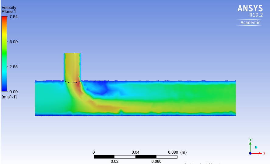
A mixing T-junction (or mixing tee) brings two fluid streams together at a 90° angle, one entering horizontally, one vertically, and forces them to mix in a common downstream channel.
In HVAC and thermal management applications, the goal is to blend a hot stream and a cold stream into a target comfort temperature. The challenge is that mixing quality is not guaranteed, poor velocity ratios or short channel lengths can leave stratified or unmixed zones at the outlet, delivering inconsistent temperatures.
Two parameters primarily control mixing effectiveness:
- Channel length, more length means more time and turbulence for the streams to homogenise
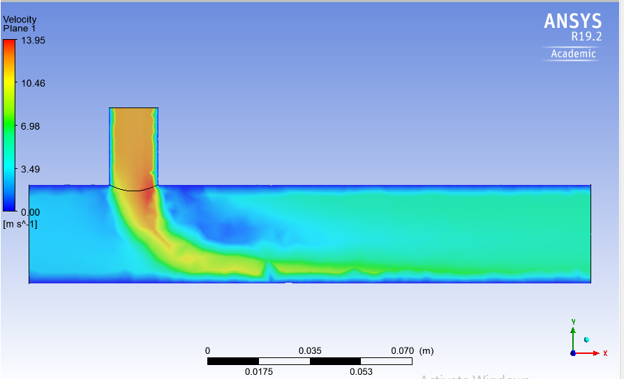
- Momentum ratio (MR), the ratio of hot-inlet velocity to cold-inlet velocity. Higher MR means the hot stream dominates and penetrates further into the cold stream, creating stronger turbulent mixing
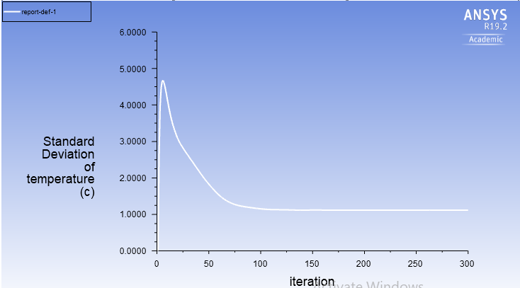
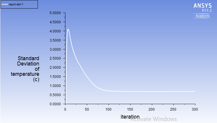
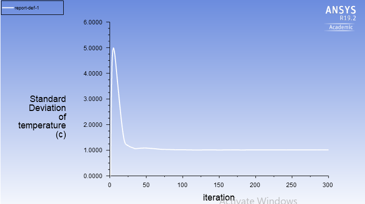
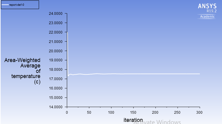
Mixing effectiveness is quantified by the standard deviation of temperature at the outlet. A low σ means the outlet temperature is uniform, good mixing. A high σ means stratification remains, poor mixing.
Physical Setup & CAD Model
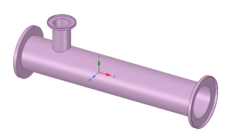
The mixing tee geometry was built in SolidWorks and imported into ANSYS Fluent. The configuration:
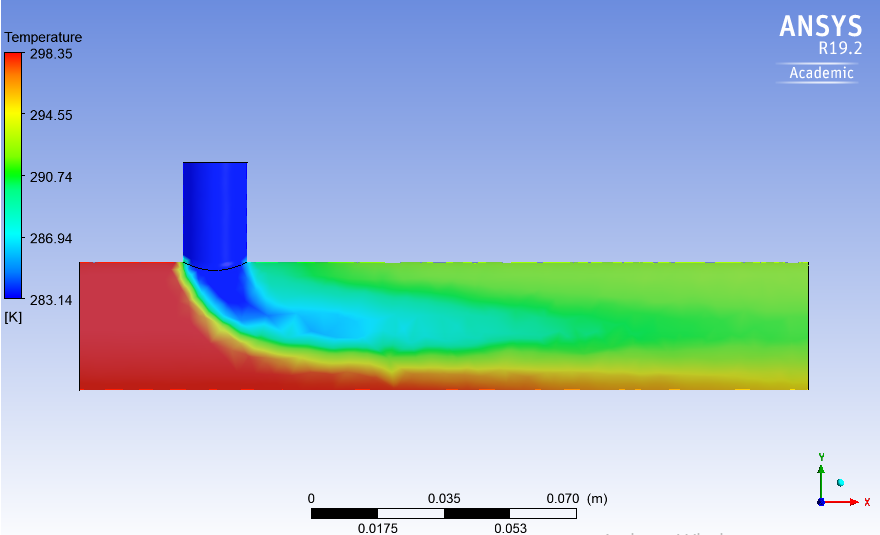
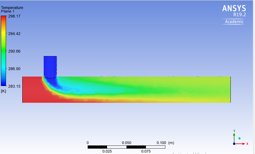
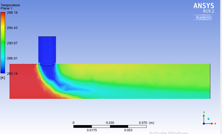
- Hot inlet (horizontal): warm airstream entering at 25 °C
- Cold inlet (vertical, 90°): chilled airstream entering at 10 °C
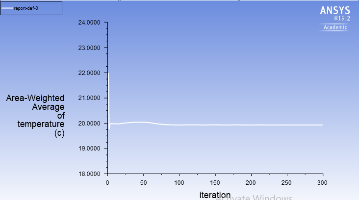
- Outlet: downstream channel where mixed air exits and temperature uniformity is measured
Boundary Conditions & Assumptions
| Parameter | Value |
|---|---|
| Hot inlet temperature | 25 °C |
| Cold inlet temperature | 10 °C |
| Hot inlet velocity (Cases 1, 2, 3) | 3 m/s |
| Momentum ratio, Cases 1 & 2 | MR = 2 (V_hot / V_cold = 2) |
| Momentum ratio, Case 3 | MR = 4 |
| Tee length, Cases 1 & 3 | Short |
| Tee length, Case 2 | Long |
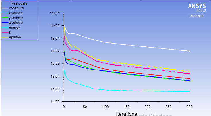
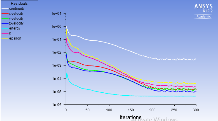
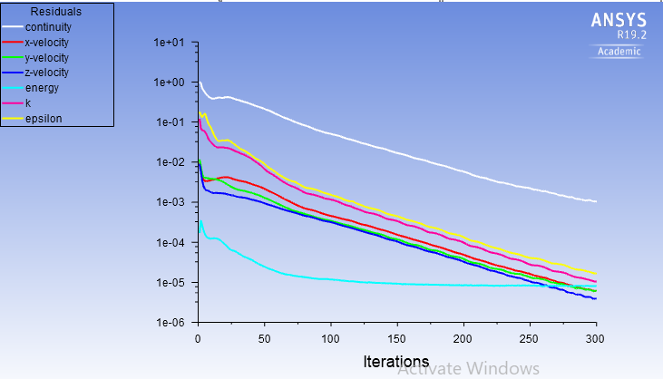
| Solver | Steady-state, pressure-based |
| Turbulence model | k-ε |
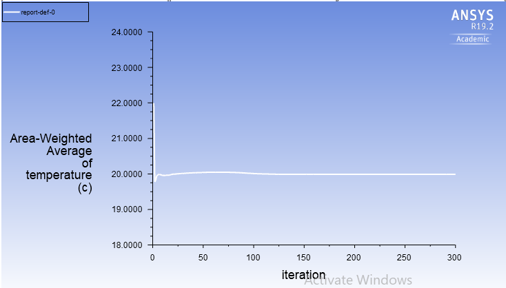
Mixing effectiveness metric: Standard deviation (σ) of temperature at the outlet cross-section. Lower σ = better mixing.
Case 1, Short Tee, MR = 2
Hot inlet velocity: 3 m/s · Cold inlet derived from MR = 2 · Short downstream channel
Case 2, Long Tee, MR = 2
Same velocity conditions as Case 1; downstream channel length increased to allow more mixing distance.
Case 3, Short Tee, MR = 4
Same short geometry as Case 1; hot inlet velocity doubled to raise momentum ratio to 4. Cold inlet velocity adjusted accordingly.
Results & Engineering Conclusions
Key findings
Channel length reduces standard deviation. The long tee (Case 2) achieved lower σ than the short tee (Case 1) at identical MR = 2. More mixing distance allows turbulence to flatten the temperature gradient before the outlet.
Higher momentum ratio improves mixing on a short tee. Case 3 (MR = 4, short) outperforms Case 1 (MR = 2, short), the stronger hot-stream penetration creates a more energetic shear layer, accelerating cross-stream mixing within the same physical length.
Both levers are independent and additive. Length and momentum ratio address mixing through different physical mechanisms, length gives the flow time to homogenise, momentum ratio increases the turbulent energy available at the junction. In a real system, either can be used depending on whether geometric constraints or flow rate control is more accessible.
| Case | Tee Length | Momentum Ratio | Outlet σ (°C) | Mixing Quality |
|---|---|---|---|---|
| 1 | Short | 2 | Baseline (highest) | Poorest |
| 2 | Long | 2 | ~0.5 | Good, length helps |
| 3 | Short | 4 | Lower than Case 1 | Good, MR helps |