Project Detail
CHT: Electronics Enclosure Cooling Optimisation
8-case SolidWorks Flow Simulation conjugate heat transfer study: fan placement, heat sink design, and airflow routing to cool a 25 W main chip and 10 W power block below 85 °C.
Key outcomes
8
Design cases, fan position, venting, heat sink geometry
61 °C
Main chip, final design at 25 W full load
60 °C
Power block, final design. Both below 85 °C target
Simulation setup
Internal forced convection with conjugate heat transfer, solid conduction and fluid convection solved together. All cases share the same boundary conditions; only fan placement, venting, and heat sink geometry change. All cases are run at basic mesh settings for quick evaluation.
Fluid
Air at 25 °C ambient, 101 325 Pa. Outer walls: 5 W/m²·K convection to ambient.
Heat loads
Cases 01-04: 10 W chip / 5 W power block. Cases 04B-08: 25 W chip / 10 W power block (full design load). Target: both below 85 °C.
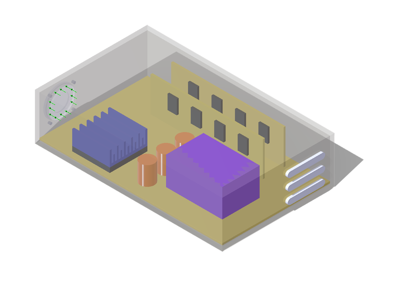
Fan
Sunon GM0535PFV1-8 (35 mm class) from the SolidWorks fan database. Fan curve applied, not a fixed flow rate.
Heat sink (initial)
Solid Al 6061 block on the main chip for Cases 01-06. Cases 07-08: finned Al heat sink, 50 × 50 mm base, 40 mm tall, 14 fins at 1 mm thick, 3.3 mm gaps.
Goals tracked
Max surface temperature on main chip and power block. Volume-averaged temperatures. Heat flow budget at enclosure walls.
Post-processing
Temperature cut plots, flow trajectories, fluid temperature, velocity cuts, surface temperature maps.
Case matrix
Each case changes one variable. Cases 01-04 ran at 10 W / 5 W to validate fan approach. Full 25 W / 10 W design load applied from Case 04B onward.
| Case | Configuration | Load | Chip (°C) | Power Block (°C) | Outcome |
|---|---|---|---|---|---|
| 01 | External inlet fan, baseline | 10 W / 5 W | 57.39 | 48.95 | Reference |
| 02 | External inlet fan + reducer shroud | 10 W / 5 W | 48.33 | 51.11 | Good chip cooling, packaging tradeoff |
| 03 | External outlet fan | 10 W / 5 W | 118.78 | 75.14 | Rejected, chip over limit |
| 04 | Internal fan | 10 W / 5 W | 50.87 | 41.72 | Selected fan approach |
| 04B | Internal fan, full design load | 25 W / 10 W | 99.80 | 65.15 | Over limit, heat sink upgrade needed |
| 05 | Internal fan + upper vent | 25 W / 10 W | 84.37 | 55.25 | Thermally OK, rejected, dust risk |
| 06 | Internal fan + rear exhaust fan | 25 W / 10 W | 95.40 | 58.48 | Rejected, worsened chip cooling |
| 07 | Internal fan + optimised Al heat sink | 25 W / 10 W | 50.89 | 84.10 | Chip fixed, power block now limiting |
| 08 | Optimised HS + cross-flow inlet fan | 25 W / 10 W | 61.07 | 59.96 | Final design, both targets met |
External inlet fan, baseline
Fan blows air directly into the enclosure from the front. Chip reaches 57.4 °C, power block 49.0 °C, both well within limit at 10 W load. Establishes the reference geometry and result for all comparisons.
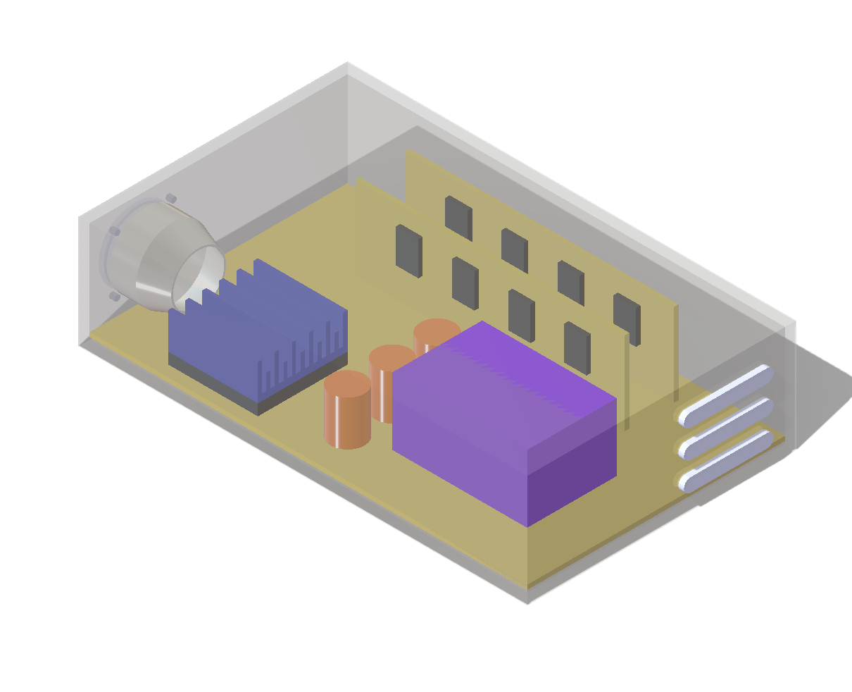
Baseline geometry, external inlet fan
Temperature cut, chip 57.4 °C, power block 49.0 °C
Flow trajectories, inlet fan drives air over components
Inlet fan + reducer shroud
A reducer shroud concentrates inlet airflow directly onto the chip heat sink. The chip improves to 48.3 °C, but the power block rises to 51.1 °C as the shroud restricts flow reaching that region. Packaging cost is also higher. Rejected as the primary path, the tradeoff between components is the wrong direction.
Reducer shroud concentrates inlet flow
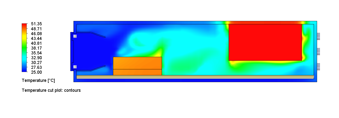
Temperature cut, chip 48.3 °C, power block rises to 51.1 °C
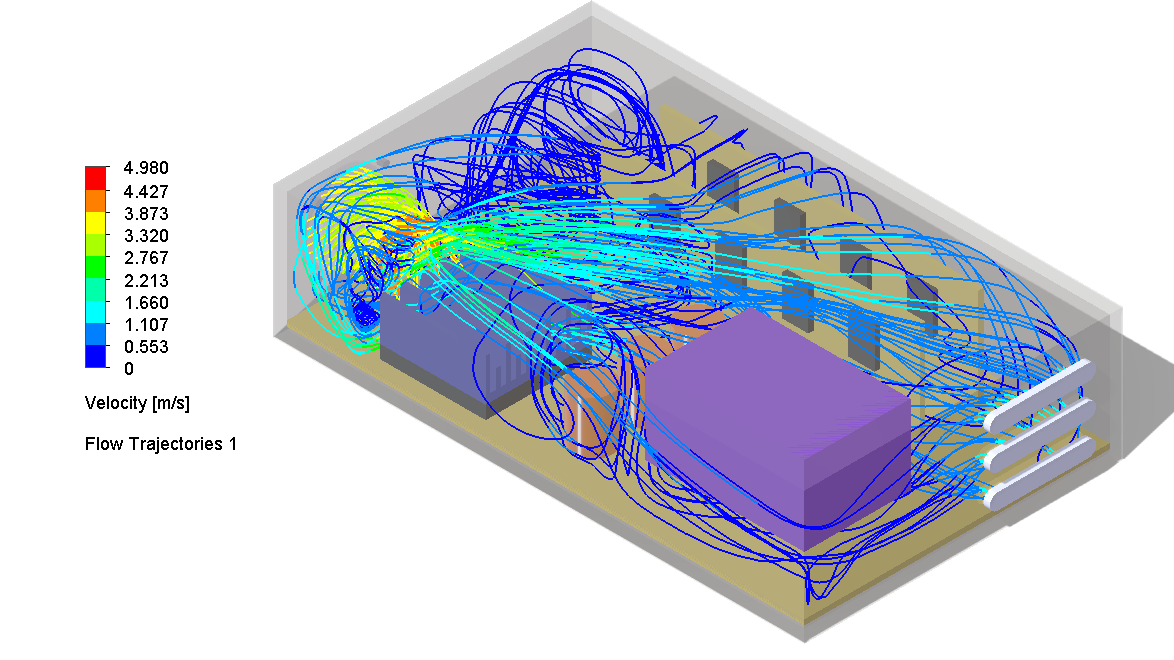
Flow trajectories, shroud channels air to heat sink, bypasses power block
External outlet fan
Fan pulls air out of the enclosure instead of pushing it in. The chip reaches 118.8 °C, 34 °C above the limit at only half the design load. Hot exhaust recirculates over the chip before it can exit. Immediately rejected.
Outlet fan geometry
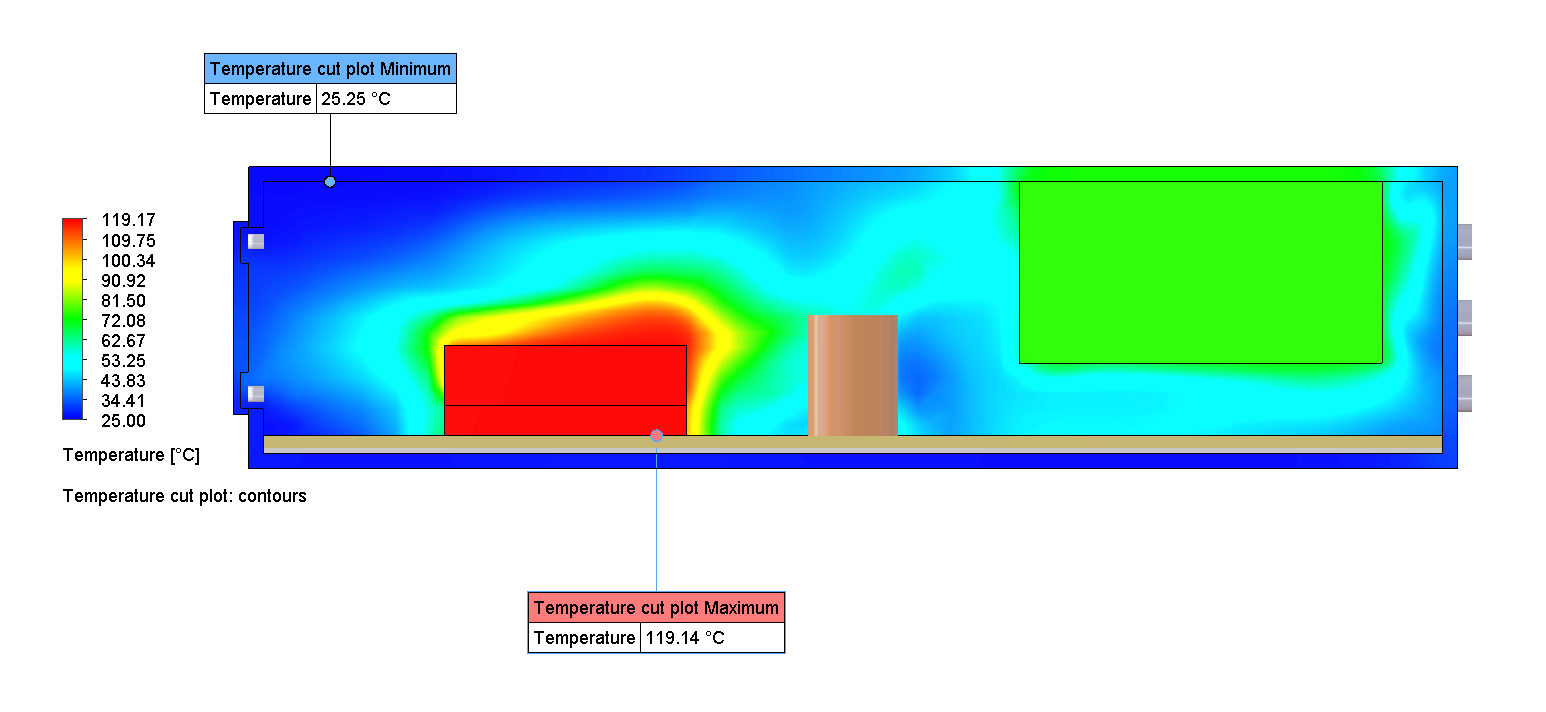
Temperature cut, chip 118.8 °C (34 °C over limit at 10 W)
Flow trajectories, hot air recirculates over chip before exiting
Key insight
Outlet vs. inlet: a 61 °C difference at the chip at the same power level. Fan direction determines whether cool air reaches the heat source before it absorbs heat from the rest of the enclosure.
Internal fan
Fan moved inside the enclosure. Chip drops to 50.9 °C and power block to 41.7 °C, the best combined result so far. Internal placement confirmed as the correct direction. The fan approach is selected; attention now shifts to whether it holds at full 25 W load.
Temperature cut, chip 50.9 °C, power block 41.7 °C
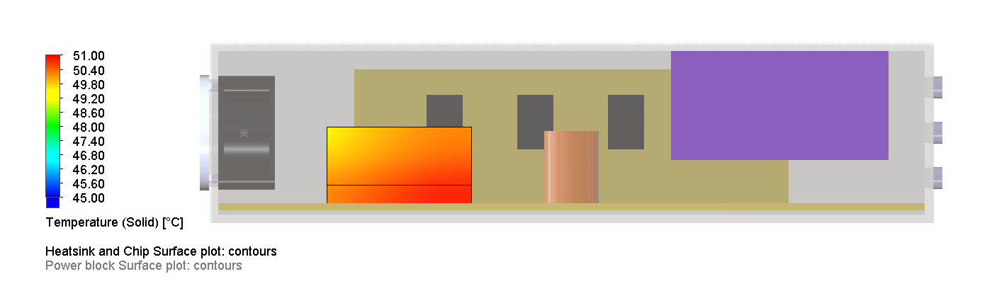
Chip and heat sink surface temperatures
Flow trajectories, internal fan drives clean air over chip and power block
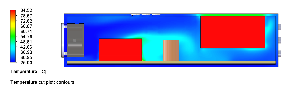
Internal fan at full design load
Same internal fan configuration as Case 04 but at the real design load: 25 W chip / 10 W power block. The chip rises to 99.8 °C, over the 85 °C limit. The fan placement is correct; the solid Al block heat sink is insufficient at full load. A finned heat sink is needed.
Fluid temperature field, at 25 W the solid block heat sink cannot keep pace (chip 99.8 °C)
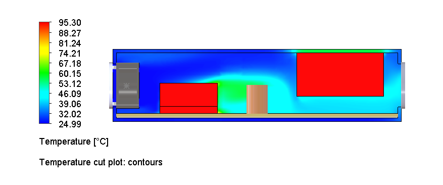
Internal fan + upper vent
An upper vent is opened to allow hot air to escape directly. The chip drops to 84.4 °C, just within the 85 °C target. However, the open aperture creates an uncontrolled dust ingress path. Rejected despite meeting the thermal target.
Temperature cut, chip 84.4 °C (meets limit but only just)
Flow trajectories, hot air exits through upper vent, but vent is open to dust
Internal fan + rear exhaust fan
A rear exhaust fan is added alongside the internal fan to increase total airflow. The chip worsens to 95.4 °C, worse than Case 04B with no second fan. The rear exhaust fan pulls air away from the heat sink before it can absorb heat from the chip. More fans, worse result.
Temperature cut, chip 95.4 °C (worse than 04B despite added fan)
Flow trajectories, rear fan pulls flow away before it reaches the chip heat sink
Finding
More fans does not mean more cooling. Airflow routing matters as much as airflow quantity, the rear fan increased total flow but reduced the fraction that reached where it was needed.
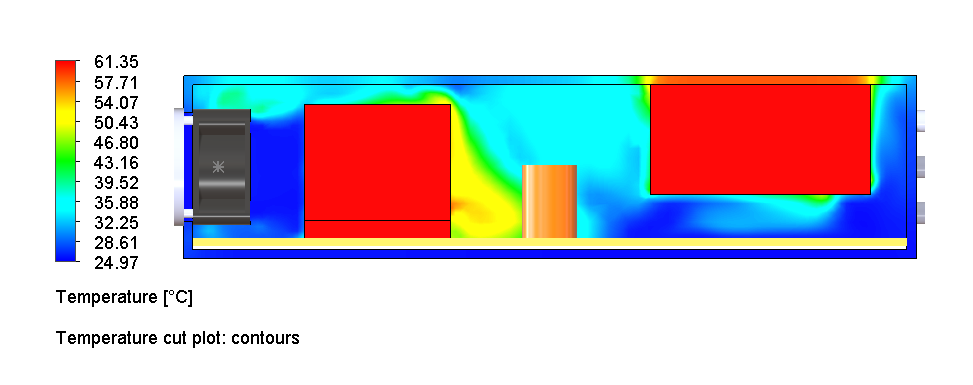
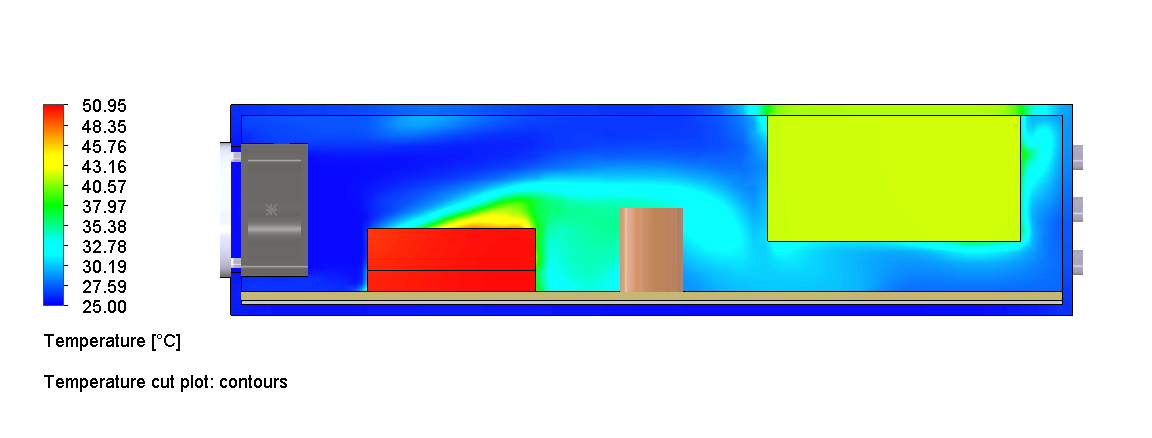
Optimised aluminium heat sink
The solid Al block is replaced with a finned heat sink: 50 × 50 mm base, 40 mm tall, 14 fins at 1 mm thick with 3.3 mm gaps. The chip drops to 50.9 °C. But the power block rises to 84.1 °C, right at the limit. The finned heat sink draws more airflow to the chip region, leaving less for the power block. Chip is no longer the bottleneck.
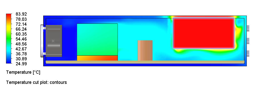
Temperature cut, chip 50.9 °C, power block 84.1 °C (at limit)
Velocity cut, high-speed airflow through fins, less reaching power block
Flow trajectories, fins pull flow; power block region is under-served
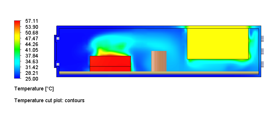
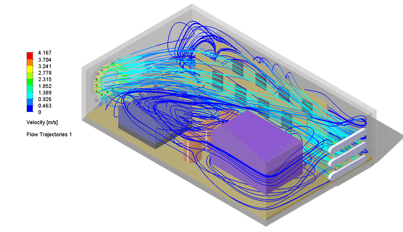
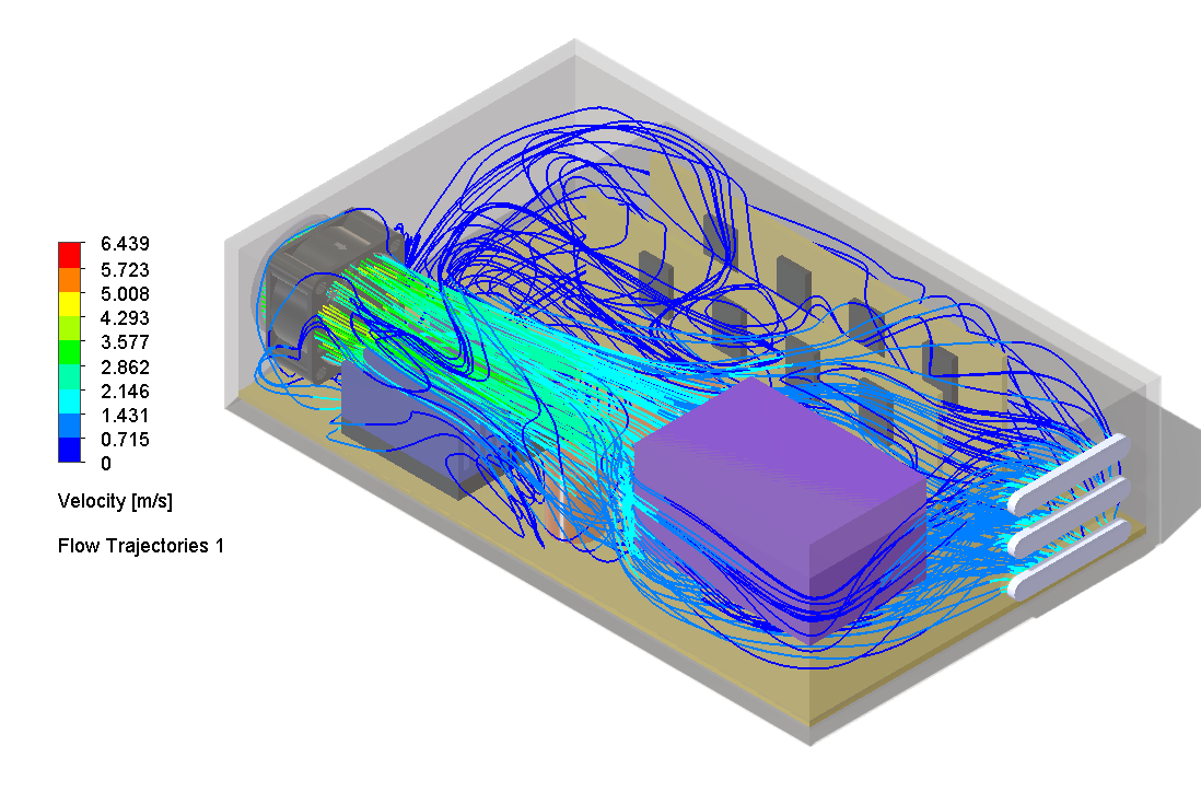
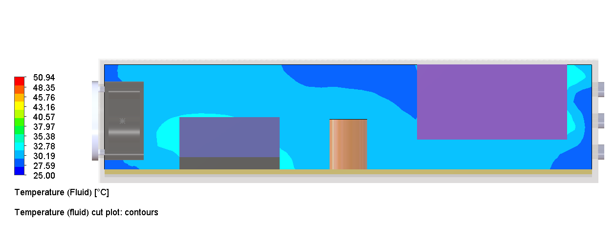
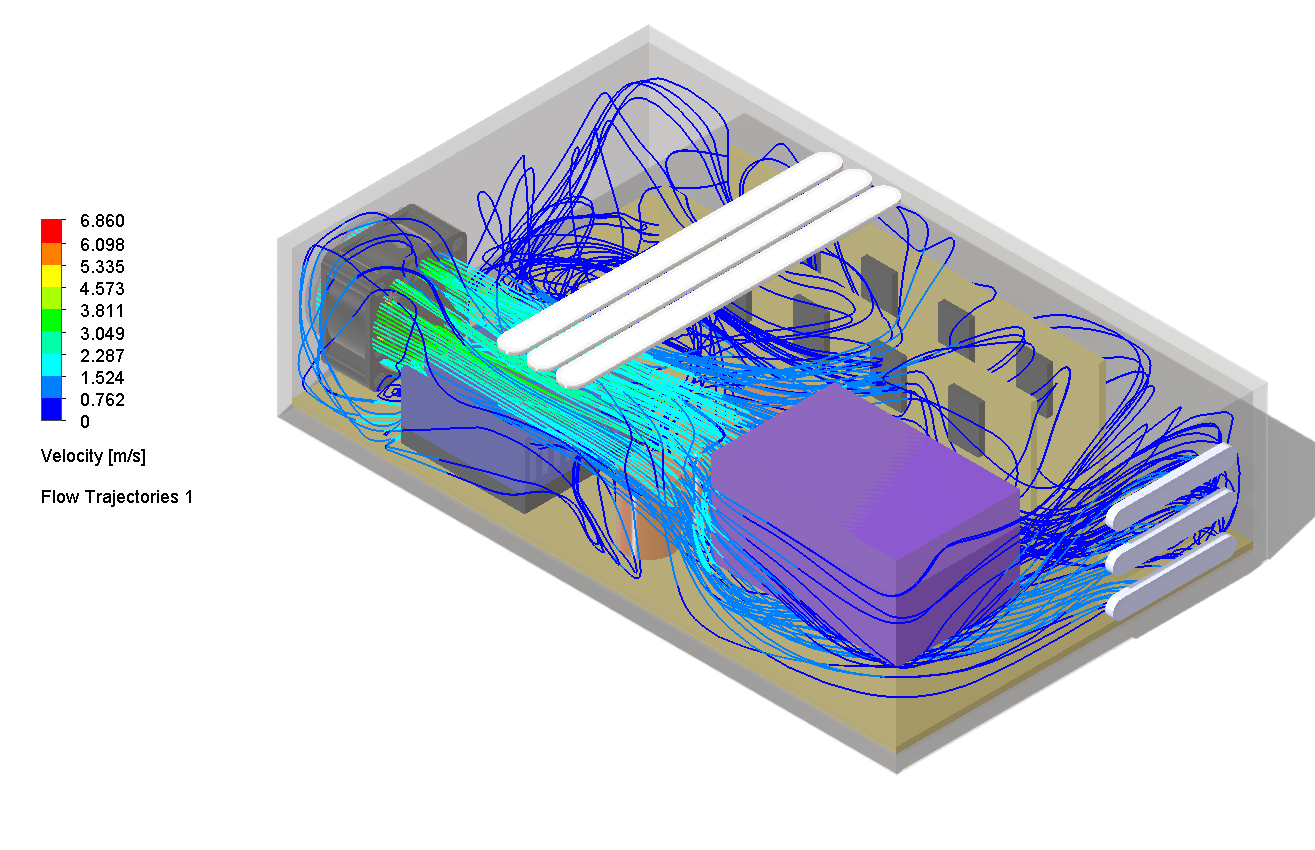
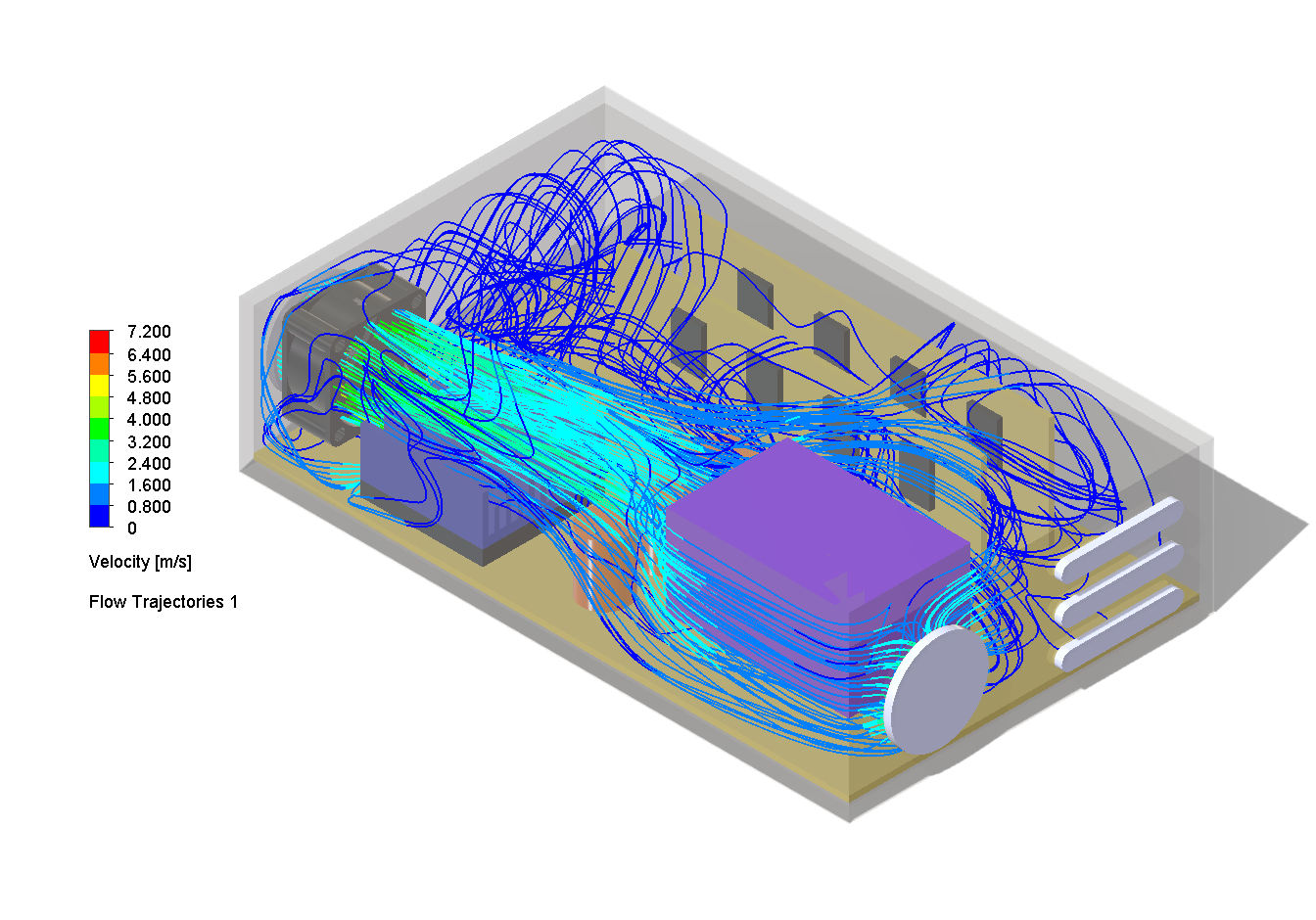
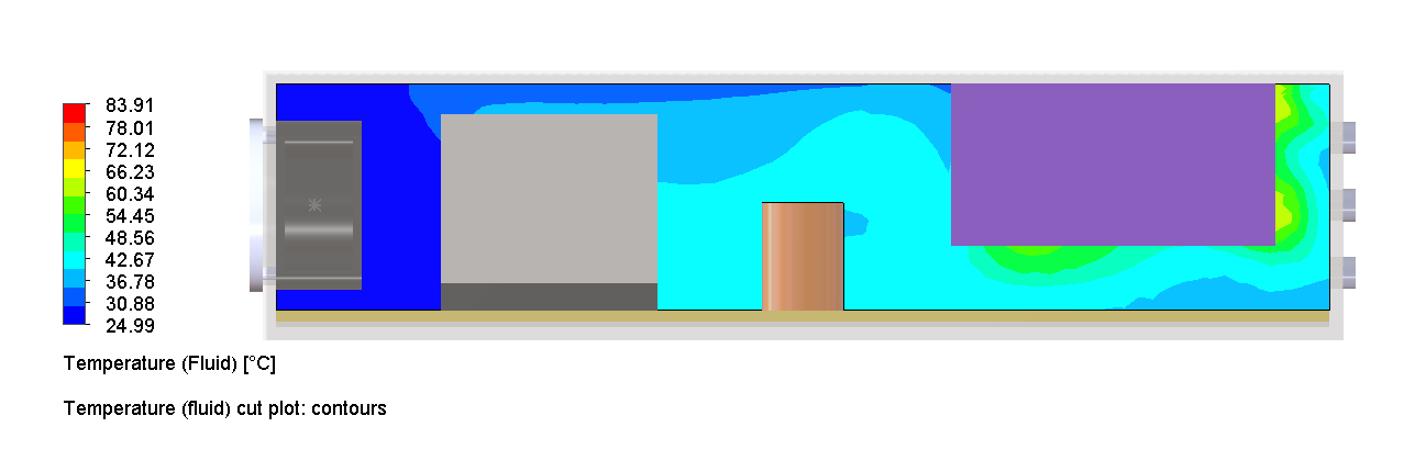
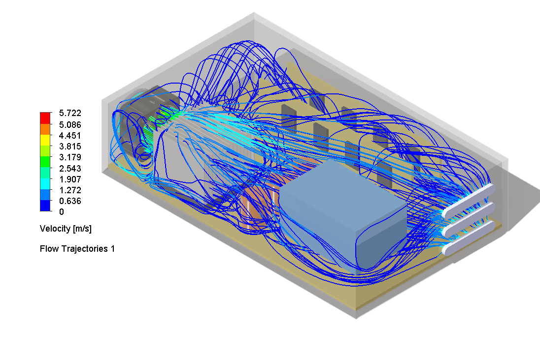
Cross-flow inlet fan, both targets met
A side-mounted cross-flow external inlet fan is added to deliver fresh air directly to the power block region. The internal fan and finned heat sink continue to manage the chip independently. Both components meet the 85 °C target with clear margin: chip 61.1 °C, power block 60.0 °C.
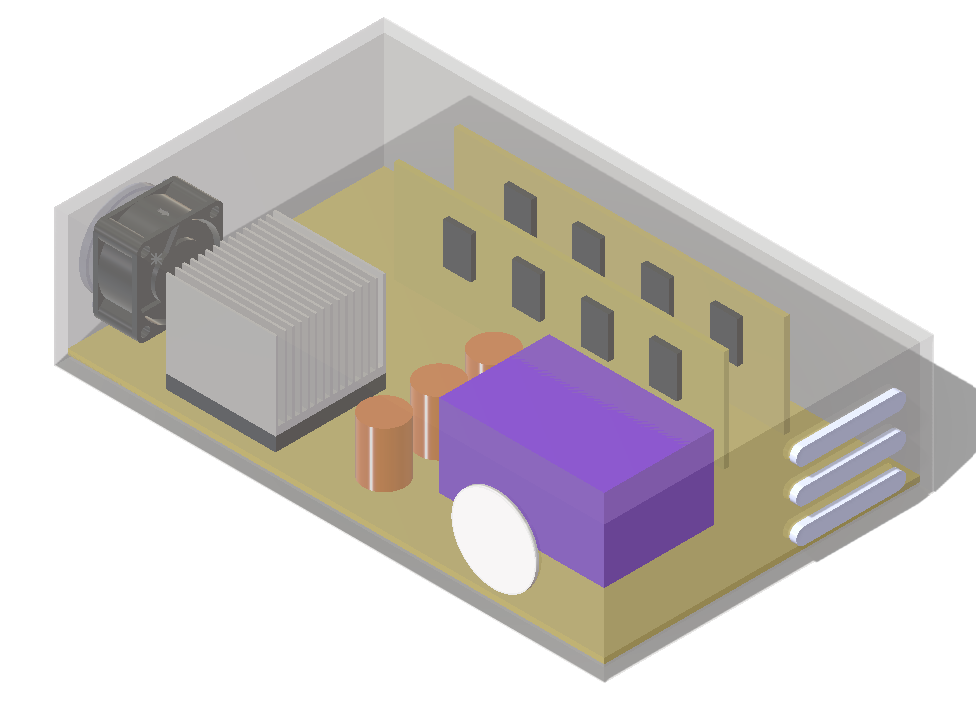
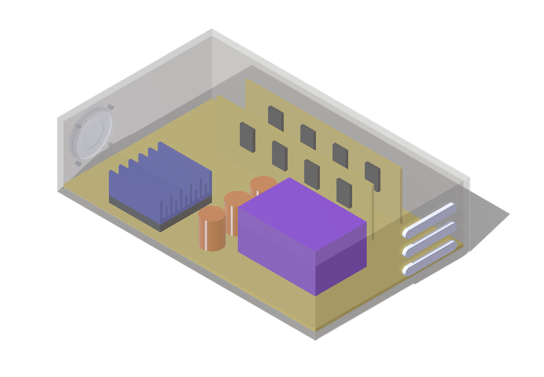
Final geometry, optimised heat sink + cross-flow inlet fan
Temperature cut, chip 61.1 °C, power block 60.0 °C

Fluid temperature, balanced thermal distribution across enclosure
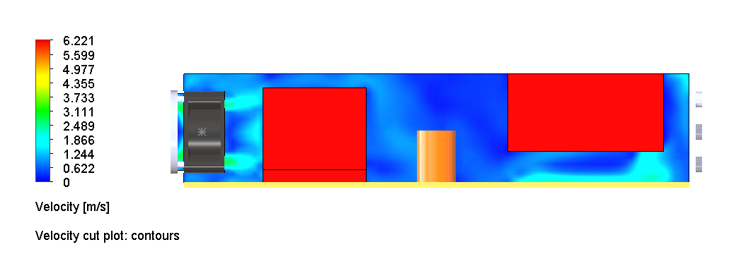
Velocity cut, dual fan airflow covering both thermal zones
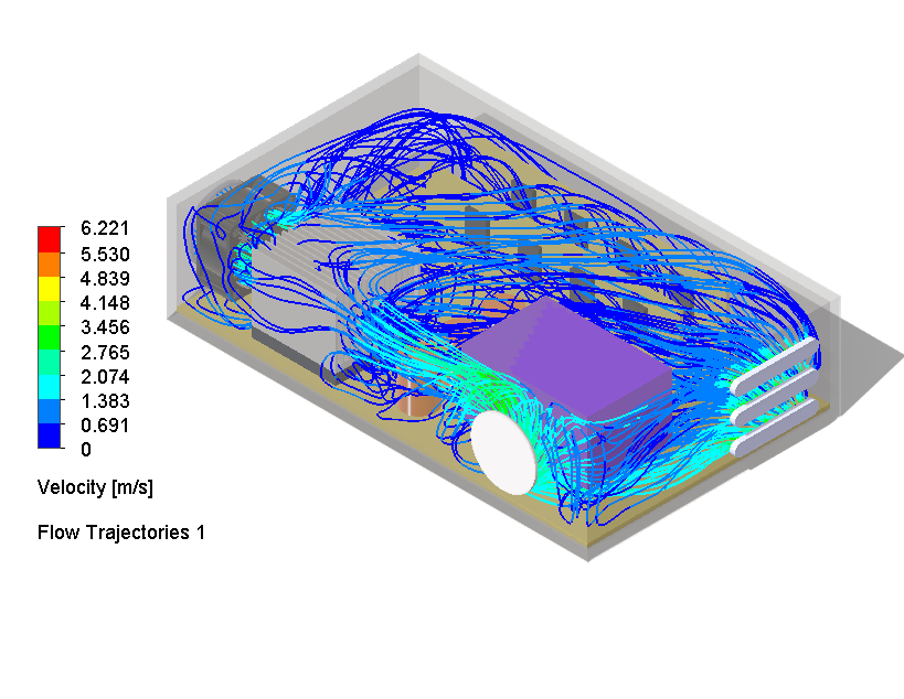
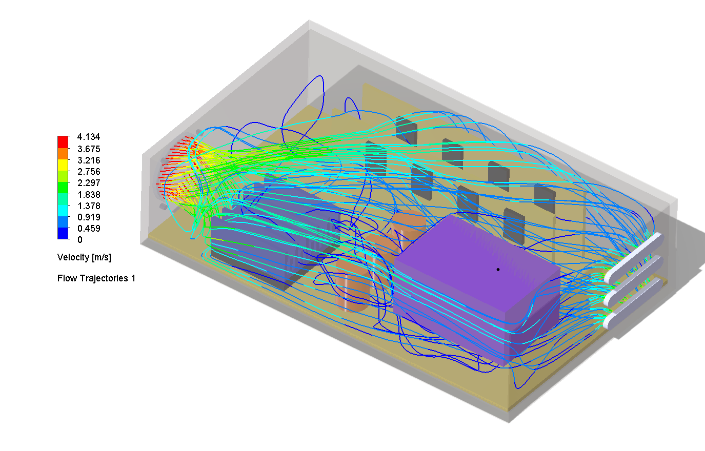
Flow trajectories, cross-flow fan delivers fresh air directly to power block region
What this study showed
The right answer wasn’t more airflow, it was airflow reaching the right place. Fan direction (Cases 03 vs 04), fan count (Case 06), and where the heat sink concentrates flow (Case 07) all shaped the outcome more than total flow rate. The 8-case progression gave a defensible, evidence-backed path to both components under target.
Where this study could go next
Case 08 meets the 85 °C target. The table below captures the most impactful next steps if power density increases or design constraints tighten.
| Optimisation | Targets | Note |
|---|---|---|
| Higher static pressure fan | Air-side convection through the heat sink | Improves flow through fin channels without adding passive dust-prone vents |
| Dedicated power block heat sink | Power block local heat rejection | Reduces dependence on airflow alone for the secondary hot component |
| Heat pipe to remote fin stack | Heat spreading and remote heat rejection | Moves chip heat to a region with better available airflow or more fin volume |
| Vapour chamber or copper spreader | Chip heat spreading | Reduces local hot spots before heat enters the fin stack |
| Filtered intake and controlled exhaust path | Dust-controlled airflow | Allows more airflow without uncontrolled open slots |
| Push-pull fan architecture | System through-flow | Can increase pressure capability if the flow path is well controlled |
| TEC feasibility study | Sub-ambient or precise temperature control | Only useful if hot-side heat rejection is upgraded; otherwise it adds heat to the system |