Project Detail
B.Tech Final Project
Capstone at K. J. Somaiya College of Engineering: designed and hand-built a large fixed-wing RC aircraft for surveillance-style operations with a high-resolution camera and fuselage volume tuned for wide-area imaging. Selected Clark Y after XFLR5 screening and Reynolds-based comparisons; analyzed lift, drag, and moment vs angle of attack at 10 m/s and corroborated with wind-tunnel testing; sized brushless power (1000 Kv, 343 W), ESC, LiPo, and servos using thrust/weight and bench thrust tests; fabricated structure from Depron foam, balsa, and boxwood directly from blueprints. Project coverage appeared in The Times of India.
At a glance
Skills & tools
Outcome
10 ft span / 3000 g RC airframe: Clark Y + XFLR5 and wind-tunnel validation, sized electric propulsion, hand-built structure; recognized in The Times of India.
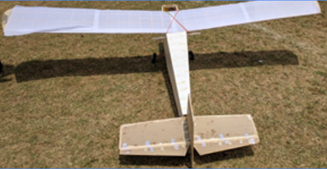
Completed RC surveillance-style airframe after fabrication and assembly, field photo from the capstone build.
10 ft
Wingspan (structural layout)
3000 g
Target all-up weight class
1000 Kv
343 W
Brushless outrunner class (sized)
Clark Y
Airfoil family for wing + control surfaces
Key figures from the engineering specification and propulsion sizing, not a substitute for formal drawings or flight logs.
Mission
The capstone was to carry a surveillance-oriented RC aircraft from requirements through analysis, electronics sizing, and hand fabrication: a high-resolution video camera for surveying large terrain, with fuselage geometry that keeps a wide field of view under the airframe.
End-to-end project phases
- Selection, Materials, airfoil family, and electronics matched to weight, speed, and mission constraints.
- Blueprint analysis, Studied and adapted existing drawings to the chosen configuration and loads.
- Computational + experimental aerodynamics, XFLR5 predictions cross-checked with wind-tunnel data on a wing model.
- Fabrication, Structural members cut and assembled by hand from traced templates.
- Assembly, Integration of structure, control surfaces, and propulsion.
Aircraft specification (design targets)
Structural targets from the project specification:
| Item | Value |
|---|---|
| Wing span | 10 ft |
| Fuselage length | 7.5 ft |
| Target weight | 3000 g |
Structural materials: Depron foam, balsa wood, and boxwood for a stiff, lightweight shell and internal structure.
Electrical architecture (representative build): brushless DC motor (1000 Kv, 343 W class), ESC, LiPo pack, and servo actuation for control surfaces.
Airfoil selection
Airfoil choice drove the wing’s aerodynamic signature. The team followed a structured screening path: compute Reynolds number for the design airspeed; pull characteristics at the design Re and Mach; compute required lift coefficient at cruise; compare drag at the design Cl across candidate sections; then rank stall behavior, Cl max, and pitching moment before locking a mission-aligned choice.
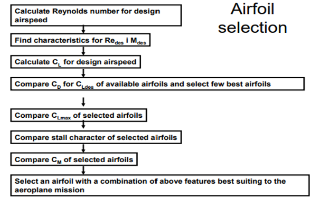
Structured airfoil down-select process (Re, Mach, Cl, Cd, stall, Cm) before mission lock-in.
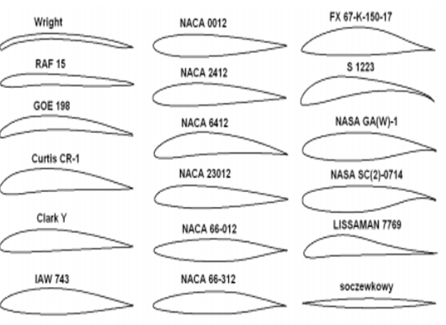
Candidate families compared side-by-side; Clark Y emerged after the screening steps above.
After calculations and side-by-side comparison of multiple families, Clark Y was selected.
Why Clark Y fit this RC mission
- High camber, Strong lift-to-drag performance for lightweight, slow RC-style flight envelopes.
- Predictable stall, Gentle separation progression, important when flying with payload and limited altitude margin.
- Deep mid-section, Room for spars, ribs, and internal routing without “paper-thin” structure compromises.
- Internal volume, Practical placement of servos (ailerons, flaps if used) and hardware without carving away primary structure.
The same Clark Y section was carried through wings, ailerons, rudder, and elevators for consistent aerodynamic behavior across the control suite.
Aerodynamic analysis and wind tunnel
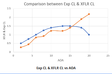
After airfoil down-select, XFLR5 was used to estimate lift, drag, and moment coefficients versus angle of attack at a 10 m/s reference speed, with curves exported for review (e.g. in Excel). The narrative matches first-principles teaching: at low angle of attack, flow stays attached and lift builds with relatively modest drag; as angle of attack increases, lift and drag both rise until the wing reaches a critical angle where upper-surface separation grows, stall, with loss of lift and a sharp drag rise if angle is not reduced.
Wind tunnel testing on a physical wing model was used to validate the software curve shapes, notably comparing experimental Cl vs XFLR Cl vs angle of attack to build confidence in the prediction stack before committing to full-scale build hours.
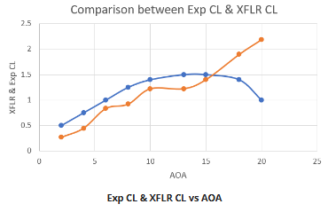
Exp Cl vs XFLR Cl vs AOA (run 1), note where simulation stall trend and tunnel data begin to diverge at higher AOA.
Companion plot from the same test campaign, used to cross-check repeatability and curve shape.
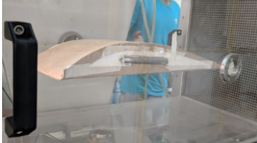
Physical model in the tunnel: ties the XFLR5 curves to measurable behavior before scaling to the full RC wing.
Electronics selection
Motor and propulsion choices were driven by a repeatable sizing thread:
- Set a target thrust-to-weight ratio for the mission.
- Translate that into total thrust required at the design weight.
- Pick a cruise speed band (slow vs fast flight style).
- Map speed preference to a Kv band (RPM per volt).
- Relate Kv to thrust-per-watt expectations.
- Compute required electrical power in watts.
- Select a commercial motor matching watts, Kv, and thrust class, then the manufacturer’s recommended propeller.
Kv vs thrust character (rule-of-thumb table used in the report)
| Kv (approx.) | Thrust efficiency (g/W band) | Speed tendency |
|---|---|---|
| 1000 | ~3.5-4.5 g/W | Slower, higher thrust feel |
| 2000 | ~2.5-3.55 g/W | Mid / higher speed |
| 3000 | ~1.8-2.5 g/W | Higher speed |
| 4000 | ~1.6-2.5 g/W | High speed, lower thrust per watt |
A thrust and power test bench tied motor + prop to a lever arm against an electronic balance, with receiver, ESC, battery, and combined current / voltage / power instrumentation to read static thrust and electrical load in one pass.
Bill of materials called out in documentation included classes such as an EMAX Simon Series 60A ESC, a 1000 Kv class brushless outrunner, Futaba servos for surfaces, and a Turnigy 5000 mAh LiPo for energy density, always subject to the exact SKU available at build time.
Fabrication and assembly
Structural parts were hand-made by tracing templates directly over blueprints, then cutting Depron, balsa, and boxwood members. Rib-and-spar style wing build and fuselage framing were aligned with jigs and adhesive process control so dihedral, incidence, and longitudinal alignment stayed within the tolerances assumed in analysis.
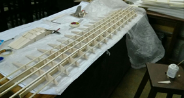
Rib-and-spar wing skeleton: material selection and DFM/DFA in how ribs index to spars and templates.
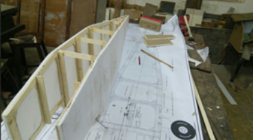
CAD-to-bench traceability: physical members checked against full-scale drawings before skinning.
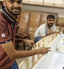
Team assembly pass on a long-span wing, scale and alignment checks under real workshop constraints.
Recognition
The team’s build and flight activity drew press interest: the project was featured in The Times of India, highlighting Mumbai student aeromodellers and the K. J. Somaiya team (coverage referenced flight demos at venues such as the Mahalakshmi Race Course). Public articles sometimes round weights or flight duration differently than lab notebooks, engineering tables in this write-up use the 3000 g specification and measured power-train data as the primary technical record.
“This is the first time we are taking up the hobby and we wish we had done so right from the first year. Everyone should pursue it… go ahead, build your own plane; it’s fascinating, learning journey.”
Lessons learned
- Software without hardware is incomplete, XFLR5 gave a fast Cl-α map, but the wind-tunnel pass caught where reality diverged from the idealized panel model.
- Propulsion is a system, Kv, prop diameter/pitch, pack voltage, and ESC current headroom have to be traded together, not as isolated catalog picks.
- Lightweight structure is detail work, tracing, cutting, and bonding hundreds of small members teaches tolerances that CAD-only courses rarely stress.
- Outcomes travel, peer recognition matters less than the engineering habits, but it validated that the build was legible to people outside the lab bench.