Project Detail
Ahmed Body: External Aerodynamics
ANSYS Fluent study on the Ahmed benchmark bluff body: multizone hexa mesh with inflation, density-based steady solver, k-ε turbulence, and a three-level grid refinement toward the academic mesh limit. Documents geometry, enclosures, residuals, drag history, and velocity/pressure/vector fields with qualitative discussion of wake resolution and wall pressure.
Background: The Ahmed benchmark
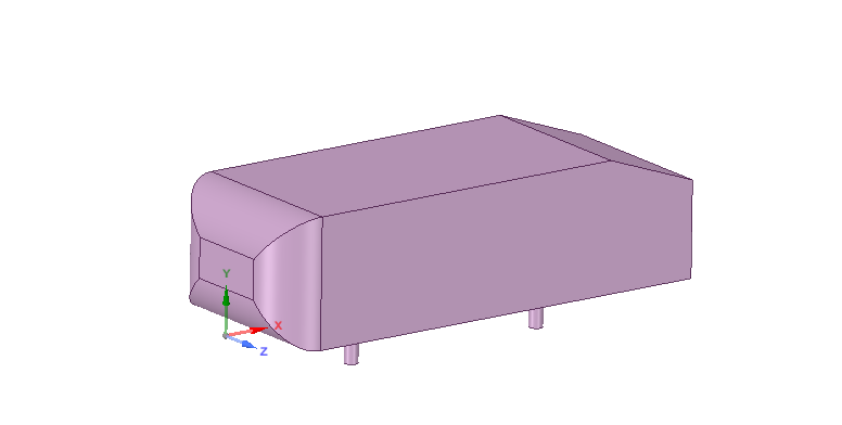
The Ahmed body was introduced by S. R. Ahmed in Some Salient Features of the Time-Averaged Ground Vehicle Wake (1984). It is a standard benchmark for automotive-style external flow: simple enough for controlled CFD studies while retaining a slanted rear deck, cylindrical supports, and a realistic bluff-body wake.
Representative dimensions (from the original study notes):
- Length ≈ 1.044 m, height ≈ 0.288 m, width ≈ 0.389 m
- 0.5 m cylindrical legs; rear slant 40° from horizontal
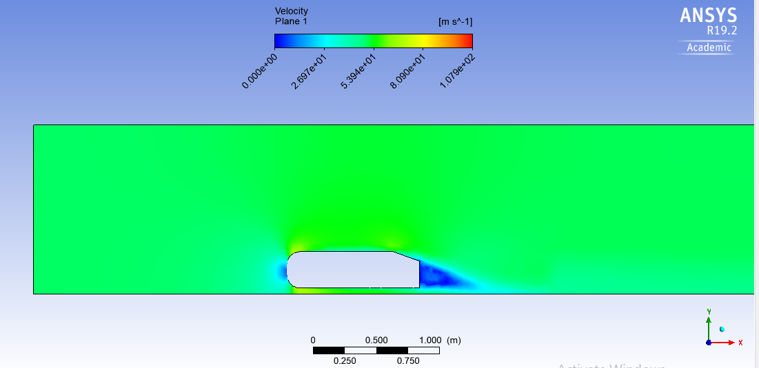
The Ahmed body is used here to predict the turbulent flow field around a simplified car geometry using a k-ε turbulence model. Typical post-processed quantities include velocity magnitude, pressure, wake structure, and force metrics (drag and lift).
Geometry and computational domain
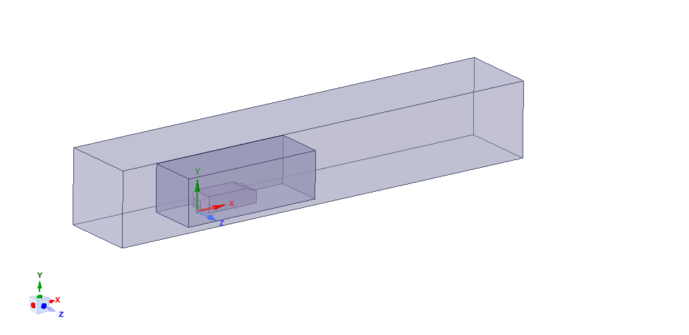
The model is enclosed so that mesh can be built outside the solid: an inner zone resolves flow over the Ahmed surface; an outer zone provides far-field extent. A grid-dependency study was planned with element counts driven toward the academic license limit (~512k cells).
Meshing and solver setup
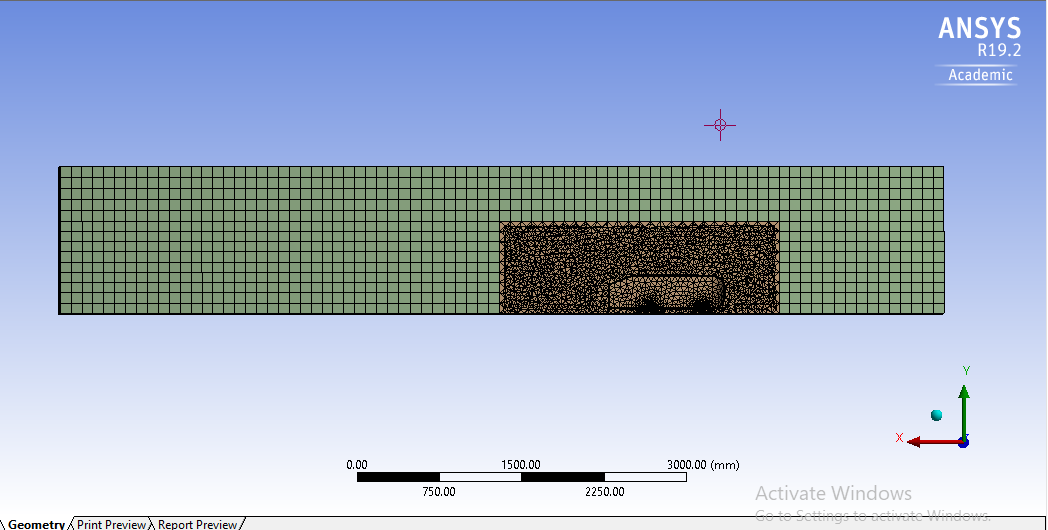
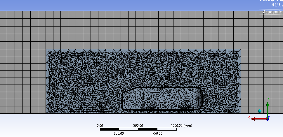
Mesh strategy
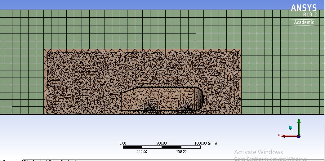
- Multizone method to separate outer and inner domains, concentrating resolution where air flows over the Ahmed body.
- Hexa-mapped mesh topology in the mesher.
- Sizing on the inner domain with three element sizes from coarser to finer for grid refinement.
- Inflation layers on the Ahmed surface to resolve the near-wall gradient.
Solver
- Steady, density-based formulation with implicit time marching (as documented in the original project notes).
Boundary conditions (documented values)
| Surface / region | Setting |
|---|---|
| Inlet | Air velocity 50 m/s |
| Inlet temperature | 300 K |
| Ahmed body walls | No-slip wall (typical external aero setup) |
| Far-field / outer boundaries | Pressure outlet / freestream extents per enclosure sizing |
Case 1 (coarser inner mesh), documented mesh metrics
| Item | Value |
|---|---|
| Inner domain element size | 50 mm |
| Cell count (inner study) | 188,471 |
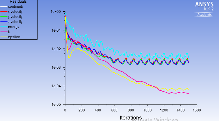
Case 1, Mesh, convergence, and force / scalar fields
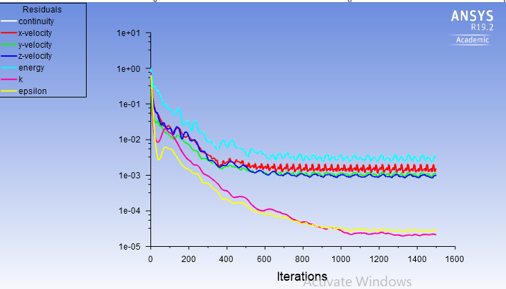
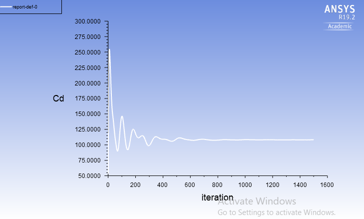
Refined mesh, additional residuals, Cd, and contours
The same post-processing sequence was repeated on a finer inner mesh (second mesh level in the grid study). Representative views:

Comments on grid dependency and results
Takeaways (from the original study text)
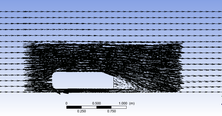
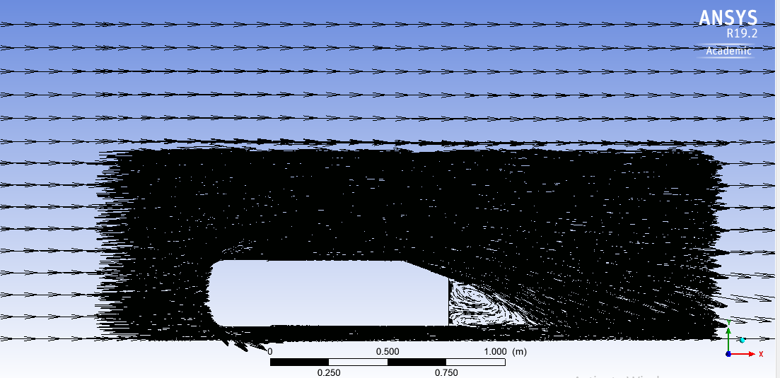
- Grid refinement smooths the solution. As inner cells are increased toward the licence limit, velocity profiles and vector plots become progressively smoother, a practical sign of reduced discretisation error.
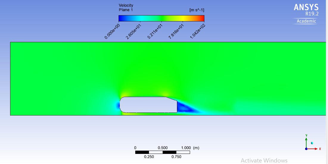
- Wake structure becomes clearer. Finer meshes resolve the wake and recirculation regions with less numerical diffusion.
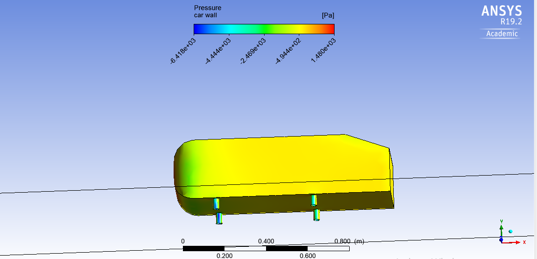
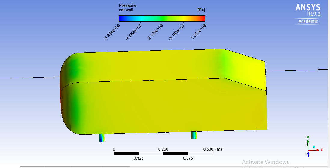
- Negative wall pressures are physical, not a solver defect. Low-pressure pockets on the legs and separated zones align with Bernoulli-type acceleration, separation bubbles, shear-related work, and recirculation, all called out explicitly in the source write-up.
Disclosure: This page migrates a legacy Google Sites export into the same long-form structure as the other ANSYS Software Studies case studies. Wording is tightened for clarity; numerical claims follow the figures and notes preserved from the original document.